Choosing the right Rotary Actuator can determine whether a machine runs smoothly or struggles with repeated downtime. In practical settings, the decision involves more than selecting torque from a product table. Engineers must examine load weight, rotation angle, speed, stopping accuracy, available space, and operating conditions. A compact actuator may fit neatly beside a conveyor, yet lack the force needed for frequent starts and stops. That detail is easy to miss.
Application experience matters. Observe the mechanism during its actual working cycle. Measure the required torque, not just the static load. Consider friction, acceleration, shock, and unexpected resistance. For example, a rotary actuator moving a gripper at 60 cycles per minute may need a larger safety margin than a lightly loaded indexing arm. Pneumatic, electric, and hydraulic designs each offer different benefits. Pneumatic models can provide fast movement and simple control. Electric units often deliver better positioning and feedback. Hydraulic systems suit demanding loads, but they may require more maintenance.
Specifications still need independent verification. Check manufacturer data, test conditions, duty ratings, sealing protection, and service recommendations. Ask whether the published torque applies throughout the complete rotation. It may not. A thoughtful selection also considers installation, noise, energy use, replacement parts, and operator safety. No catalog can predict every factory condition. That is why prototype testing and consultation with qualified engineers remain valuable. The best choice is not always the strongest or cheapest model. It is the actuator that performs reliably, fits the system, and leaves room for real-world uncertainty.
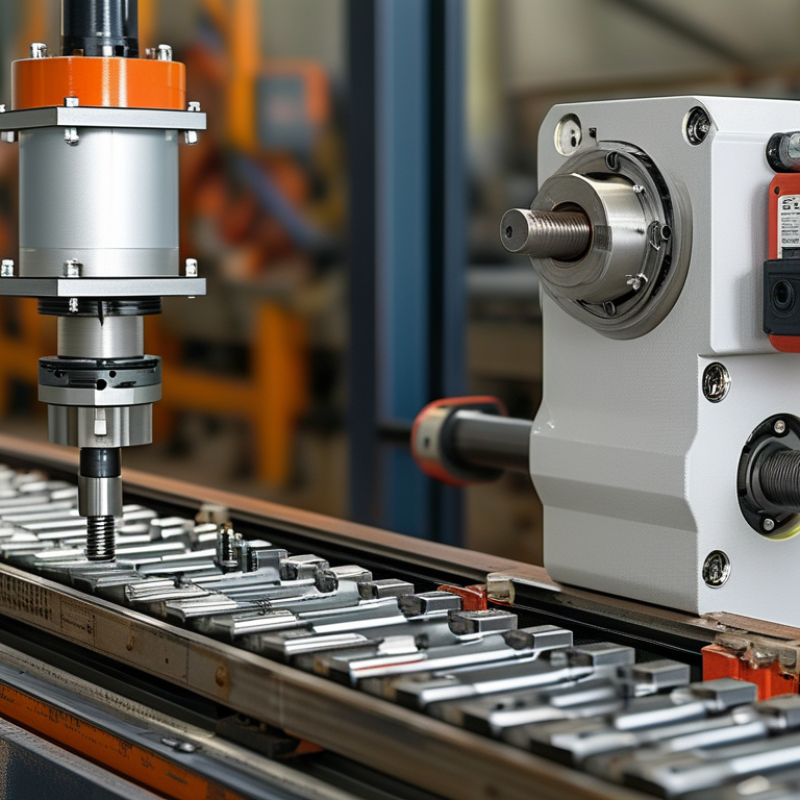
Before choosing a rotary actuator, define exactly how the shaft must move.
Is the motion continuous, limited-angle, oscillating, or indexing? Write the target angle, speed, acceleration, and stopping position. These details prevent a torque-only selection.
Small details matter.
Record the driven load, transmission ratio, shaft orientation, and available installation space. A quarter-turn valve may require only 90 degrees, but controlled acceleration still matters. An indexing table demands different timing and repeatability.
Calculate the required torque from the load torque, friction, acceleration, and transmission losses. Include the load’s inertia, especially when the shaft starts and stops quickly. Add a sensible safety margin, but avoid choosing an oversized unit without checking response time.
Excess capacity can increase cost, energy use, and positioning difficulty.
I have seen designs pass static torque checks yet stall during rapid reversal. The missing factor was acceleration.
Define performance with measurable limits.
Specify allowable backlash, repeatability, positioning accuracy, duty cycle, and acceptable settling time. Consider whether the actuator must hold position without power. Check the operating temperature, dust, moisture, and shock exposure.
These conditions can change lubricant behavior and reduce rated performance. A spreadsheet may look precise while relying on uncertain friction values. Test a representative load when possible.
Observe overshoot, vibration, heat buildup, and noise during repeated cycles. Then review the assumptions before finalizing the actuator size.
Choosing a rotary actuator starts with its operating principle, not its catalogue size. Electric actuators use motors, gearboxes, and position feedback for clean, programmable motion. Pneumatic actuators convert compressed-air pressure into fast quarter-turn movement, often for valves and simple indexing. Hydraulic actuators deliver the highest force density, but they require pumps, fluid management, and stricter maintenance.
The drive method should match the load profile. Select electric systems when positioning accuracy, quiet operation, and data feedback are important. Choose pneumatic systems for rapid, repetitive end positions where compressed air already exists. Hydraulic systems suit heavy loads, shock forces, or harsh duty cycles. The International Federation of Robotics reported 541,302 industrial robot installations in 2023, showing continued demand for repeatable motion and integrated control. However, robotics data does not automatically justify an electric actuator; a small valve may still need only a compact pneumatic unit.
Check torque at startup, not only during steady rotation. Include breakaway torque, friction, inertia, cycle frequency, and safety margin. ISO 5211 mounting dimensions can simplify valve-actuator compatibility, but they do not confirm correct performance. Energy use deserves attention too. The International Energy Agency estimates motor-driven systems consume more than 40% of global electricity, so inefficient sizing can remain expensive for years. A practical test is simple: record cycle time, air pressure or current draw, and surface temperature during real production. One overlooked issue is oversizing. More torque feels safer, yet it can reduce control quality, waste energy, and increase mechanical stress.
Choosing the Right Rotary Actuator: Calculate Torque, Speed, Load, and Duty Cycle Needs
Choosing a rotary actuator starts with measurements, not catalog pictures. Measure the load, mounting radius, and motion angle on the actual machine. Torque equals force multiplied by distance from the shaft. Add friction, acceleration, and a safety margin of 25 to 50 percent. A 20-newton load on a 0.15-meter arm needs 3 newton-meters before losses. It is easy to underestimate the arm.
Speed needs equal attention. Define the rotation angle and target cycle time, then calculate speed as angle divided by time. A 90-degree move in 0.5 seconds requires 180 degrees per second. Check performance under the real torque load. Rated no-load speed can mislead. Include acceleration and deceleration, because abrupt stops create shock and vibration. In testing, record cycle time with the payload attached, rather than relying only on published data.
Duty cycle describes how often the actuator works and rests. Calculate operating time divided by total cycle time, then compare it with the thermal rating. Ten seconds of motion in a 40-second cycle equals a 25 percent duty cycle. Consider starts per hour, ambient temperature, and holding torque. A unit may meet peak torque but overheat during repeated cycles. My first estimate is rarely perfect; cable drag, worn bearings, and misaligned loads can change the result. Recheck measurements after installation.
| Parameter | What to Determine | Typical Unit | Why It Matters | Recommended Design Margin |
|---|---|---|---|---|
| Required torque | Torque needed to start, move, stop, and hold the load under the worst operating condition | N·m | The actuator must provide sufficient continuous and peak torque without overheating or stalling | Apply a factor of 1.25–1.50 to calculated running torque |
| Rotational speed | Required angular speed and the time allowed for the specified rotation angle | rpm or °/s | Determines cycle time, gearbox ratio, motor speed, and acceleration requirements | Allow additional time for acceleration, deceleration, and control response |
| Inertia | Load moment of inertia, including tooling, coupling, and reflected gearbox inertia | kg·m² | High inertia increases acceleration torque and may cause overshoot or vibration | Confirm the actuator inertia ratio against the manufacturer’s allowable value |
| Axial and radial load | External forces acting along or perpendicular to the output shaft | N | Excessive shaft loading can reduce bearing life or cause premature mechanical failure | Use external support bearings when loads exceed the actuator’s shaft capacity |
| Duty cycle | Operating time, idle time, cycles per hour, and average torque over the working period | % or cycles/hour | Controls thermal load, motor heating, seal life, and long-term reliability | Use continuous-duty sizing when operation is frequent or heat dissipation is limited |
| Operating environment | Temperature, humidity, dust, washdown, corrosion, and hazardous-area requirements | °C, IP rating | Determines enclosure, materials, lubrication, seals, and control protection | Select an environmental rating above the actual site conditions |
| Torque Component | Formula | Variables | Example | Result |
|---|---|---|---|---|
| Horizontal linear load | T = F × r | F = tangential force in N; r = lever arm in m | F = 180 N, r = 0.20 m | 36 N·m |
| Gravity load | T = m × g × r | m = mass in kg; g = 9.81 m/s²; r = horizontal distance from shaft center in m | m = 25 kg, r = 0.30 m | 73.6 N·m |
| Friction torque | T = μ × FN × r | μ = coefficient of friction; FN = normal force in N; r = effective radius in m | μ = 0.08, FN = 1,200 N, r = 0.10 m | 9.6 N·m |
| Acceleration torque | T = J × α | J = total inertia in kg·m²; α = angular acceleration in rad/s² | J = 0.18 kg·m², α = 12 rad/s² | 2.16 N·m |
| Combined required torque | Ttotal = Tload + Tfriction + Tacceleration | Include all torque components acting at the same time | 73.6 + 9.6 + 2.16 N·m | 85.36 N·m |
| Selection torque with margin | Tselect = Ttotal × safety factor | Typical safety factor: 1.25–1.50 | 85.36 × 1.35 | 115.24 N·m minimum |
| Required Information | Formula | Example Input | Calculated Value | Selection Consideration |
|---|---|---|---|---|
| Angular speed in degrees per second | ω = θ ÷ t | θ = 90°, t = 0.75 s | 120°/s | Confirm that the actuator can reach the target speed after acceleration |
| Angular speed in rpm | rpm = θ × 60 ÷ (360 × t) | θ = 90°, t = 0.75 s | 20 rpm | Use the actual movement time, excluding dwell time |
| Cycle time for a fixed speed | t = θ ÷ ω | θ = 180°, ω = 60°/s | 3.0 s | Add acceleration, deceleration, settling, and control delays |
| Angular acceleration | α = ω ÷ ta | ω = 10 rad/s, ta = 0.5 s | 20 rad/s² | Higher acceleration increases torque demand and mechanical stress |
| Output power estimate | P = T × ω | T = 40 N·m, ω = 2.09 rad/s | 83.6 W | Motor input power must be higher after efficiency and thermal losses |
| Operating Pattern | Movement Time | Rest or Dwell Time | Approximate Duty Cycle | Typical Sizing Approach |
|---|---|---|---|---|
| Occasional indexing | 2 seconds per cycle | 58 seconds per cycle | 3.3% | Intermittent-duty actuator may be suitable if peak torque and starts per hour are within limits |
| Moderate production cycle | 8 seconds per cycle | 22 seconds per cycle | 26.7% | Check average torque, starts per hour, and motor temperature rise |
| Frequent reciprocating motion | 15 seconds per cycle | 5 seconds per cycle | 75% | Prefer continuous-duty capability with adequate heat dissipation |
| Continuous rotation | Continuous | None | 100% | Use a continuous-duty actuator and verify continuous torque at the required speed |
| Check | Acceptance Requirement | Example Target | Status |
|---|---|---|---|
| Continuous torque | Rated continuous torque is greater than the calculated running torque | Rated torque ≥ 85.36 N·m | Required |
| Peak or acceleration torque | Peak torque exceeds the maximum short-duration torque demand | Peak torque ≥ 115.24 N·m | Required |
| Output speed | Available speed covers the required operating speed without exceeding limits | Required speed: 20 rpm | Required |
| Positioning accuracy | Repeatability and absolute accuracy meet the process requirement | Repeatability: ±0.1° or better | Application-dependent |
| Load capacity | Radial, axial, and overhung loads remain below rated shaft and bearing limits | Verify all external forces and moments | Required |
| Duty and thermal rating | Actuator can operate at the required duty cycle without exceeding allowable temperature | Duty cycle: 75% | Required |
| Environment and protection | Enclosure, temperature range, sealing, and materials match the installation site | Example: IP65 for dust-tight and water-jet protection | Application-dependent |
| Control compatibility | Voltage, feedback, communication, braking, and emergency-stop requirements are compatible | 24 VDC control with position feedback | Required |
| Application Requirement | Suitable Actuator Category | Primary Advantage | Main Limitation to Check |
|---|---|---|---|
| Simple two-position movement with moderate force | Pneumatic rotary actuator | Fast operation and simple control | Limited positioning flexibility and compressed-air consumption |
| Accurate positioning and programmable motion | Electric servo rotary actuator | High control accuracy and adjustable speed profiles | Higher system cost and control complexity |
| Compact indexing with fixed positions | Electric stepper-based rotary actuator | Simple open-loop positioning for suitable loads | Possible loss of position under overload or excessive acceleration |
| High torque at low output speed | Geared rotary actuator | Increases output torque and reduces speed | Backlash, efficiency loss, and gearbox thermal limits |
| Continuous rotation under stable load | Continuous-duty rotary drive | Designed for sustained operation | Continuous thermal rating and bearing life |
Choosing a rotary actuator starts with the environment, not the catalog torque. Define temperature, humidity, dust, washdown pressure, vibration, and chemical exposure. An IP66 enclosure resists dust and powerful water jets, according to IEC 60529. It does not prove resistance to solvents or saltwater. That distinction matters.
Control requirements need equal attention. Record load torque, travel angle, cycle frequency, speed, stopping accuracy, and available voltage. A 24 VDC system may simplify installation, but voltage drop can reduce actuator performance over long cables. Feedback also changes the decision. Position sensors, limit switches, or torque monitoring can support safer control. The International Federation of Robotics reported 541,302 industrial robots installed worldwide in 2023. This growth increases demand for repeatable motion and reliable integration, not merely higher output.
Installation details often decide whether the actuator survives. Check mounting space, shaft alignment, cable bend radius, service access, and heat transfer. In a dusty packaging area, leave room for cleaning without directing spray at cable entries. In a freezer, specify low-temperature seals and suitable lubricants. A first choice can still fail when brackets flex or loads create side force. I would not overlook that. Review the actuator with the entire mechanism, controller, wiring, and maintenance schedule. Then test the real duty cycle, including pauses, starts, and emergency stops.
Choosing a rotary actuator should begin with evidence, not a catalog photograph. Review the required torque, rotation angle, speed, repeatability, duty cycle, and installation space. Then identify the driven load, including inertia, friction, center of gravity, and stopping method. These details often expose hidden demands. An actuator rated for peak torque may still struggle during frequent reversals. Leave a realistic safety margin.
Testing should reproduce the real operating cycle as closely as possible. Mount the actuator with the actual linkage, load, and control settings. Measure starting torque, movement time, position accuracy, temperature, vibration, and noise. Run repeated cycles, not just one successful demonstration. Watch the first minutes and the warmest operating period. Small errors become important over time. Record results under low, normal, and maximum expected loads.
Specification review is equally important. Check whether the listed performance applies to continuous duty, specific supply conditions, or controlled laboratory testing. Confirm shaft dimensions, mounting tolerances, feedback options, ingress protection, and maintenance requirements. Ask how performance changes after extended cycling. No test is perfect. Real systems surprise us. A better selection comes from comparing measured behavior with documented limits, then questioning any gap before installation. Reliability is not claimed; it is demonstrated through repeatable testing and clear records.
: Start with the operating principle and real load requirements. Check torque, angle, speed, repeatability, duty cycle, and available space. A catalogue photograph proves very little.
Choose electric systems for accurate positioning, quiet motion, and feedback data. They use motors, gearboxes, and control signals. They may be unnecessary for a simple valve.
Pneumatic systems suit fast, repetitive, quarter-turn movements. They work well where compressed air is already available. Think of repeated stops at two fixed positions.
Hydraulic systems suit heavy loads, shock forces, and harsh duty cycles. They provide high force in a compact space. However, pumps and fluid maintenance add complexity.
Check startup torque carefully. Include breakaway torque, friction, inertia, and frequent reversals. Steady rotation may hide the hardest movement.
Use a realistic margin based on measured conditions. Oversizing can waste energy, reduce control quality, and increase mechanical stress. More torque is not always safer.
Test the real linkage, load, and control settings. Measure cycle time, starting torque, position accuracy, temperature, vibration, and noise. Run repeated cycles. One successful movement proves little.
Check mounting dimensions, shaft details, tolerances, feedback options, protection levels, and maintenance needs. Confirm the stated performance conditions. Laboratory results may not match production behavior.
Record air pressure or electrical current during real cycles. Also monitor surface temperature and cycle frequency. A smaller actuator might perform better, but this should be tested.
Choosing the right Rotary Actuator begins with clearly defining the required motion, positioning accuracy, rotation range, speed, and repeatability. Determine whether the application needs continuous rotation, limited-angle movement, precise stopping, or controlled acceleration and deceleration. Then compare available actuator types, drive methods, and operating principles to identify the solution that best matches the machine’s performance goals, control system, and available power source.
Before making a selection, calculate the required torque, operating speed, load characteristics, inertia, acceleration time, and duty cycle. Environmental conditions such as temperature, dust, moisture, vibration, and installation space must also be considered, along with maintenance access and safety requirements. Finally, review technical specifications carefully and test the actuator under realistic operating conditions. Evaluating motion quality, heat generation, noise, energy use, and long-term reliability will help confirm that the selected actuator can deliver stable performance and support the application throughout its service life.

Stepper Motor